03 / ASSEMBLE THE SWARM
Choose a shape.
Give it power.
A row, a wall, a cluster. Build a physical arrangement that suits the behaviour you want to explore.
Calculate your power ↓Our reference is sixteen nodes in a 4×4 grid. The idea is modular; the current firmware still assumes sixteen.
01 / ARRANGEMENT
Sixteen is
a starting point.
The reference swarm uses sixteen nodes to give enough variation in behaviours to approximate a real swarm. A 4×4 grid makes that activity easy to see and compare.
Physical arrangements can be smaller, larger, rectangular or split into clusters. Each panel keeps its own ESP32, memory and identity. HUB75 carries display data inside a node; it does not turn the flock into one daisy-chained screen.
CURRENT SOFTWAREThe public Korvo implementation uses sixteen roster entries and 4×4 coordinates. A different count or topology needs corresponding firmware, identity and UI work. Calculator values above sixteen are planning scenarios, not supported-fleet claims.
Current roster and coordinate implementation ↗02 / POWER BUDGET
Count the nodes.
Then the amps.
Plan at 5 V DC. The default panel allowance is 4 A (20 W), plus an editable electronics allowance for each node. These are design inputs, not a measurement of your wall.
5 V DC CAPACITY TARGET
90A450 W
- Per node, including electronics
- 4.5 A / 22.5 W
- Total load allowance
- 72 A / 360 W
- Headroom above load
- 18 A / 90 W
- One supply’s usable output
- 60 A / 300 W
2 separately powered zones: 8 + 8 nodes.
Each zone budgets 36 A load and 45 A capacity, including headroom. At most 10 complete nodes fit this supply budget.
USB-C · 5 V / 3 A COMPARISONA single node needs 5.63 A including headroom. A 3 A rail is below this budget.
Below the 4 A reference: use the verified rating of your exact panel or a measured worst case at a reliably enforced brightness limit. A slider setting alone does not establish that limit.
Assumptions & calculation
Load current = nodes × (panel allowance + electronics allowance). Capacity target = load × (1 + headroom / 100). DC watts = 5 × amps.
The controller host, its screen, optional WLED controller and ARGB lighting are excluded: supply and budget those separately. Include speaker peaks and added peripherals in the per-node electronics allowance.
Zone count respects whole nodes: floor(supply amps ÷ per-node capacity target) nodes per supply. Counts are balanced across separate zones. Supplies are not paralleled.
Use the supply’s derated usable output for the actual temperature, mounting and ventilation. This is a DC capacity estimate; it does not calculate AC input, conversion losses, branch fuses, wire gauge, voltage drop or transient response.
The old panel wiki lists 3 A alongside ≤20 W; the current manufacturer lineup lists 4 A. The 4 A default avoids sizing from the lower, conflicting figure. Confirm your actual panel batch.
03 / CHOOSE THE SUPPLY
Read the 5 V line.
Not the headline.
A dedicated regulated 5 V DC supply is the normal wall-build route. The LRS-350-5 example is rated 5 V, 60 A, 300 W. “350” is the series name, not this model’s 5 V output power.
Its AC input uses a 115/230 V selector, with specified ranges covering typical 120/240 V mains. It is an enclosed component supply, not a complete touch-safe appliance. Mains termination, protective earth, branch protection and enclosure work belong with a qualified installer.
USB-C can serve a limited bench node.
The project runs a single panel through the Waveshare POWER USB-C port from 5 V / 3 A with brightness limited to about 30%, using the board-to-panel power lead. Verify actual peak demand and enforce the limit. The calculator defaults to the full panel rating; it does not infer current from brightness percentage. Use the single-node power instructions for the two connection paths.
A high-wattage USB-C charger often supplies only 5 V / 3 A (15 W) on its 5 V profile. Its larger advertised wattage is available at higher negotiated voltages. That does not make it a high-current 5 V panel supply.
Three amps is not a universal USB-PD limit: specialist supplies can offer more, such as Raspberry Pi’s 5.1 V / 5 A supply. That requires a compatible negotiated power path, suitable cable and verified load-voltage tolerance; it is not a drop-in recommendation for this board.
DO NOT SUBSTITUTE VOLTAGENever feed a negotiated 9, 12, 15 or 20 V output directly into a 5 V panel. A higher-voltage PD source requires a separately engineered 5 V converter and protection. Do not join charger ports to add their current ratings.
04 / DISTRIBUTE & MOUNT
Short branches.
Known limits.
- Draw a low-voltage distribution plan. Assign each node to one supply zone and label both ends of every branch.
- Use individually protected branches, with fuse and conductor ratings selected for the cable, connectors, length and load. A 60 A supply does not protect a small branch lead by itself.
- Keep each supply’s positive output separate. Do not parallel LRS-350-5 outputs; use separate node groups. Any signal-ground relationship must follow the actual interface design.
- Provide strain relief, ventilation, insulated terminals and service access. Check mounting holes and cable clearance against your actual panels.
- Measure voltage at the furthest panel under the intended worst-case load. Resolve excessive drop by improving distribution, not by exceeding panel voltage limits.
Four nodes make a tile.
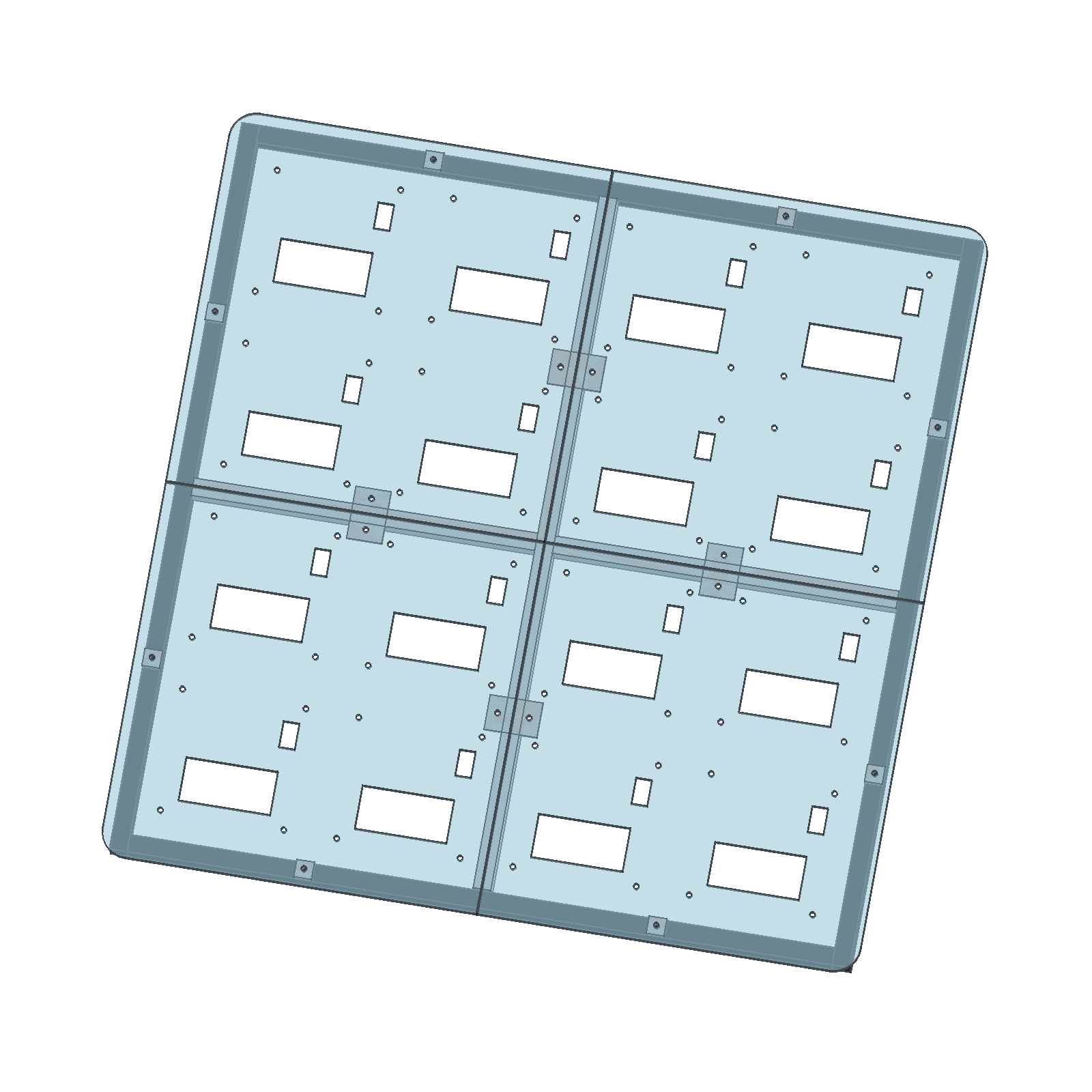
Build a 2×2 group on a laser-cut acrylic carrier, then arrange several tiles into a wall, a row or another formation. The reference model uses four tiles for sixteen nodes. Each tile supports four distinct panels with deliberate space between them.
The current CAD uses tiles up to 429.25 × 429.25 × 6 mm, 200 mm node pitch and 1.5 mm central seams, making an 860 mm square reference carrier. These are the model’s trial dimensions. Alternative formations need their own rear frame, edge treatment, wiring and mounting design.
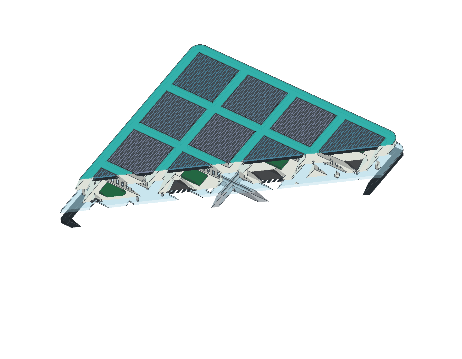
Source CAD: four 2×2 acrylic carrier tiles.
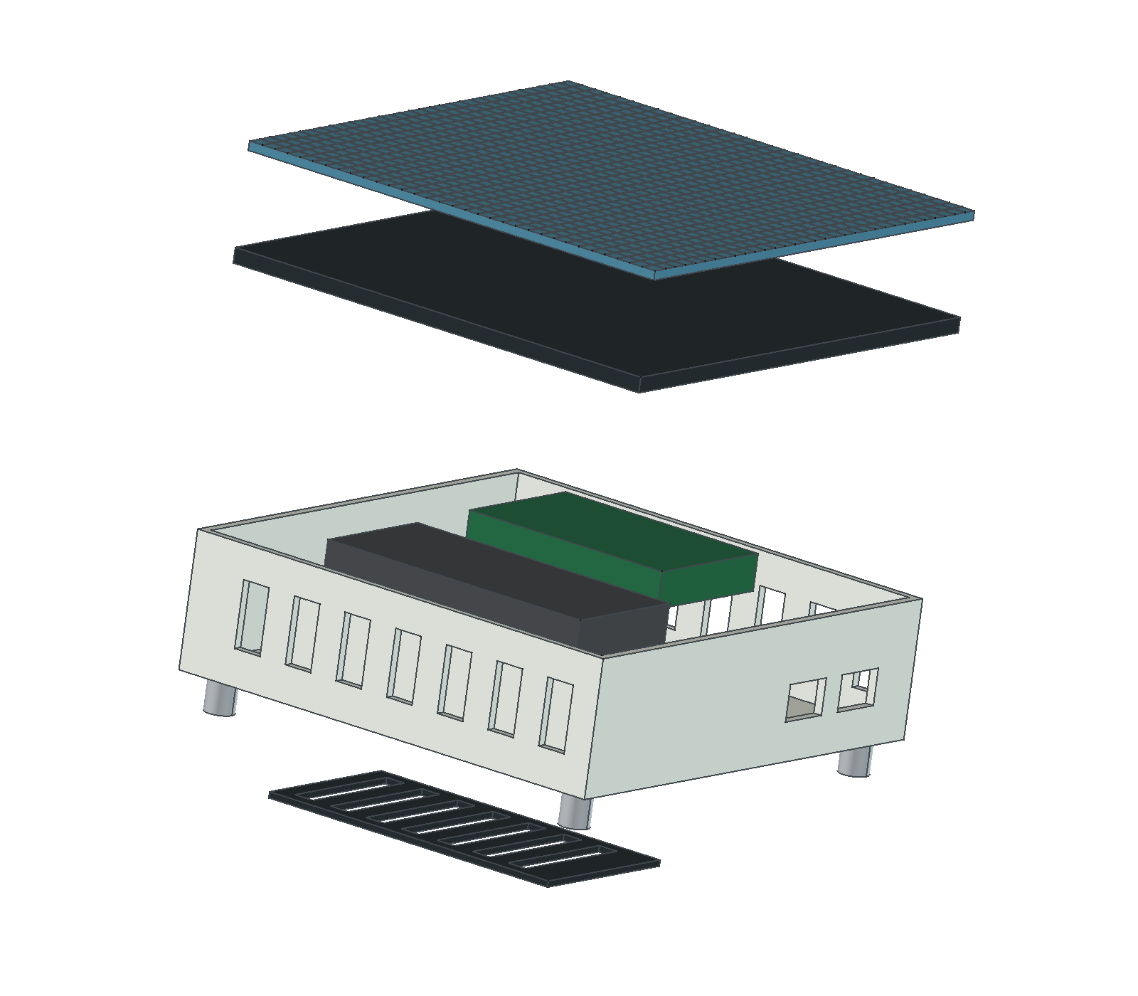
The viewer preserves the published raised-panel CAD geometry, including its trays, speaker envelopes, braces and channel network. Electronics blocks and some holes in this older concept remain placeholders. The single-node guide uses the newer board drawing. Row and cluster views rearrange source tiles; they are layout studies, not released mounting kits.
Assembly layers & source mockups
Temporary joins. Permanent support.
Printed joiners let nodes be temporarily joined for experiments. For a permanent installation, carry the weight through a designed rear frame and suitable wall or stand attachment. Acrylic separates and locates the nodes; neither acrylic thickness nor printed joints alone establish a load rating.
Optional light between the nodes.
A 3D-printed channel grid is intended to carry addressable RGB (ARGB) lighting, with WLED visualising node communications between panels. The current visible cue is flashing panel borders, so the flock works without this lighting layer. Treat the WLED link as an optional experiment that needs its own controller, integration and power budget.
The public CAD includes the project’s support studies and adaptations. Purchased track/diffuser meshes were removed from the public layout files; those files are not a complete printable lighting-channel kit.
The 250 mm and 199.8 mm pitches in the public CAD are layout candidates. They are not a universal mounting standard or a verified wall enclosure.
Mounting studies and their maturity ↗05 / JOIN THE FLOCK
Bring them up
one at a time.
Complete the single-panel acceptance checks first. Give each physical node its own identity, then add it to the controller roster. For the reference build, match A1–D4 to the actual row and column.
Configure the documented local network and radio channel. Power zones can be separate while nodes communicate wirelessly; HUB75 remains between each ESP32 and its own panel.
A normal scene at 25% brightness is not a full-load acceptance test. Do not infer electrical headroom from appearance or multiply the full-brightness current by the brightness slider percentage.
Provisioning and per-node acceptance ↗Back to the three build guides ↗